- 您现在的位置:买卖IC网 > Sheet目录475 > MAX9635ESA+ (Maxim Integrated)IC AMBIENT LIGHT SENSOR 8NSOIC
�� �
�
�Industry’s� Lowest-Power�
�Ambient� Light� Sensor� with� ADC�
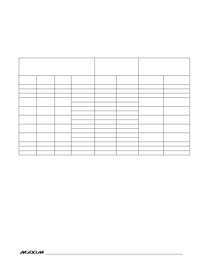
�Table� 9.� Recommended� Manual� Mode� Settings� for� Configuration� Register� (0x02)� and�
�Threshold� Registers� (0x05,� 0x06)�
�APPLICATION� CONDITIONS�
�RECOMMENDED� SETTINGS�
�FOR� CONFIGURATION�
�REGISTER� (0x02)�
�RANGE� OF� EXPONENTS� FOR�
�UPPER� AND� LOWER�
�THRESHOLD� REGISTERS�
�(0x05� AND� 0x06)�
�LUX� LSB�
�(MIN)�
�0.045�
�0.09�
�0.18�
�0.36�
�0.72�
�1.44�
�2.88�
�5.76�
�11.52�
�23.04�
�46.08�
�LUX�
�(MAX)�
�2938�
�5875�
�11,750�
�23,501�
�47,002�
�94,003�
�188,006�
�188,006�
�188,006�
�188,006�
�188,006�
�LUX� LSB�
�(MAX)�
�11.52�
�23.04�
�46.08�
�92.16�
�184.32�
�368.64�
�737.28�
�737.28�
�737.28�
�737.28�
�737.28�
�INTEGRATION�
�TIME� (ms)�
�800�
�400�
�200�
�100�
�800�
�50�
�400�
�25�
�200�
�12.5�
�100�
�6.25�
�50�
�25�
�12.5�
�6.25�
�TIM[2:0]�
�000�
�001�
�010�
�011�
�000�
�100�
�001�
�101�
�010�
�110�
�011�
�111�
�100�
�101�
�110�
�111�
�CDR�
�0�
�0�
�0�
�0�
�1�
�0�
�1�
�0�
�1�
�0�
�1�
�0�
�1�
�1�
�1�
�1�
�EXPONENT�
�(MIN)�
�0000�
�0001�
�0010�
�0011�
�0100�
�0101�
�0110�
�0111�
�1000�
�1001�
�1010�
�EXPONENT�
�(MAX)�
�1000�
�1001�
�1010�
�1011�
�1100�
�1101�
�1110�
�1110�
�1110�
�1110�
�1110�
�Note:� In� manual� mode,� exceeding� the� lux� (max)� causes� an� overload� error� (exponent� =� 1111).�
�Typical� Operating� Sequence�
�To� utilize� the� ultra-low� power� consumption� of� the� IC� in�
�end� applications,� an� interrupt� pin� is� provided� to� eliminate�
�the� need� for� the� system� to� poll� the� device� continuously.�
�Since� every� clock� and� data� bit� transmitted� on� I� 2� C� can�
�consume� up� to� 1mA� (assuming� 1.8k� I� pullup� resistor� to�
�a� 1.8V� rail),� minimizing� the� number� of� I� 2� C� transactions�
�on� the� data� bus� can� save� a� lot� of� power.� In� addition,�
�eliminating� the� need� to� poll� the� device� frees� up� process-�
�ing� resources� for� the� master,� improving� overall� system�
�performance.�
�The� typical� sequence� of� communication� with� the� IC� is�
�as� follows:�
�1)� Master� reads� lux� reading� from� registers� 0x03� and�
�0x04.�
�2)� Master� sets� the� upper� lux� threshold� and� lower� lux�
�threshold� in� registers� 0x05� and� 0x06� so� that� a� user-�
�programmed� window� is� defined� around� the� current�
�lux� readings.�
�3)� Master� sets� suitable� threshold� timer� data� in� register�
�0x07.�
�4)� Master� works� on� other� tasks� until� alerted� by� the� INT�
�pin� going� low.� This� is� where� the� master� spends� much�
�of� its� time.�
�5)� When� alerted� by� the� INT� pin� going� low,� the� master�
�reads� the� Interrupt� Status� register� 0x00� to� confirm�
�the� source� of� interrupt� was� the� IC.� The� master� takes�
�appropriate� action.�
�6)� Repeat� from� Step� 1.�
�13�
�发布紧急采购,3分钟左右您将得到回复。
相关PDF资料
MAX9930EVKIT+
KIT EVAL FOR MAX9930
MAX9947ETE+
TXRX AISG INTEGRATED 16TQFN
MAX9981ETX+D
IC MIXER DUAL SIGE 36-QFN
MAX9981EVKIT
EVAL KIT FOR MAX9981
MAX9982ETP+D
IC MIXER HI LINEAR SIGE 20-TQFN
MAX9982EVKIT
EVAL KIT FOR MAX9982
MAX9984ETP+T
IC MIXER DOWN CONV 20-TQFN
MAX9985ETX+T
IC MIXER DOWN CONV DUAL 36-TQFN
相关代理商/技术参数
MAX9635ESA+T
功能描述:环境光传感器 Ambient Light Sensor
RoHS:否 制造商:Vishay Semiconductors 工作电源电压: 峰值波长:570 nm 最大工作温度:+ 85 C 最小工作温度:- 40 C 封装 / 箱体:T-1 封装:Bulk
MAX9635EVKIT
功能描述:光学传感器开发工具 MAX9635 Eval Kit RoHS:否 制造商:ams 工具用于评估: 接口类型: 最大工作温度:
MAX9635EVKIT#
功能描述:环境光传感器 Industry’s Lowest-Power Ambient Light Sensor with ADC RoHS:否 制造商:Vishay Semiconductors 工作电源电压: 峰值波长:570 nm 最大工作温度:+ 85 C 最小工作温度:- 40 C 封装 / 箱体:T-1 封装:Bulk
MAX9635EVKIT+
功能描述:光学传感器开发工具 MAX9635 Eval Kit RoHS:否 制造商:ams 工具用于评估: 接口类型: 最大工作温度:
MAX9636AXT+
制造商:Maxim Integrated Products 功能描述: 制造商:Maxim Integrated Products 功能描述:3V/5V LOW-POWER LOW-NOISE RAIL-TO-RAIL I/O OP AMP (SINGLE CH - Rail/Tube
MAX9636AXT+T
功能描述:运算放大器 - 运放 3V-5V Low-Power Op Amp RoHS:否 制造商:STMicroelectronics 通道数量:4 共模抑制比(最小值):63 dB 输入补偿电压:1 mV 输入偏流(最大值):10 pA 工作电源电压:2.7 V to 5.5 V 安装风格:SMD/SMT 封装 / 箱体:QFN-16 转换速度:0.89 V/us 关闭:No 输出电流:55 mA 最大工作温度:+ 125 C 封装:Reel
MAX9636EVKIT+
功能描述:放大器 IC 开发工具 MAX9636 Eval Kit RoHS:否 制造商:International Rectifier 产品:Demonstration Boards 类型:Power Amplifiers 工具用于评估:IR4302 工作电源电压:13 V to 23 V
MAX9637AXA+
制造商:Maxim Integrated Products 功能描述:OPERATIONAL AMPLIFIER - Rail/Tube